the motor is the PCB (axial-flux BLDC)
My final year project. A brushless motor with no iron and no wound coils — the stator is just a circuit board with copper spirals on it.
what it earned350 rpm/V built · zero cogging
aug 2026 – now · solo · on the bench · prototype
Normally a motor’s stator is iron with copper wound around it. This one is a 100 mm circuit board. The windings are copper spirals etched into the two layers — six wedge-shaped coils over eight poles, wired as a three-phase star. Then a 3D-printed rotor either side holding eight magnets each, across a 0.5 mm air gap.
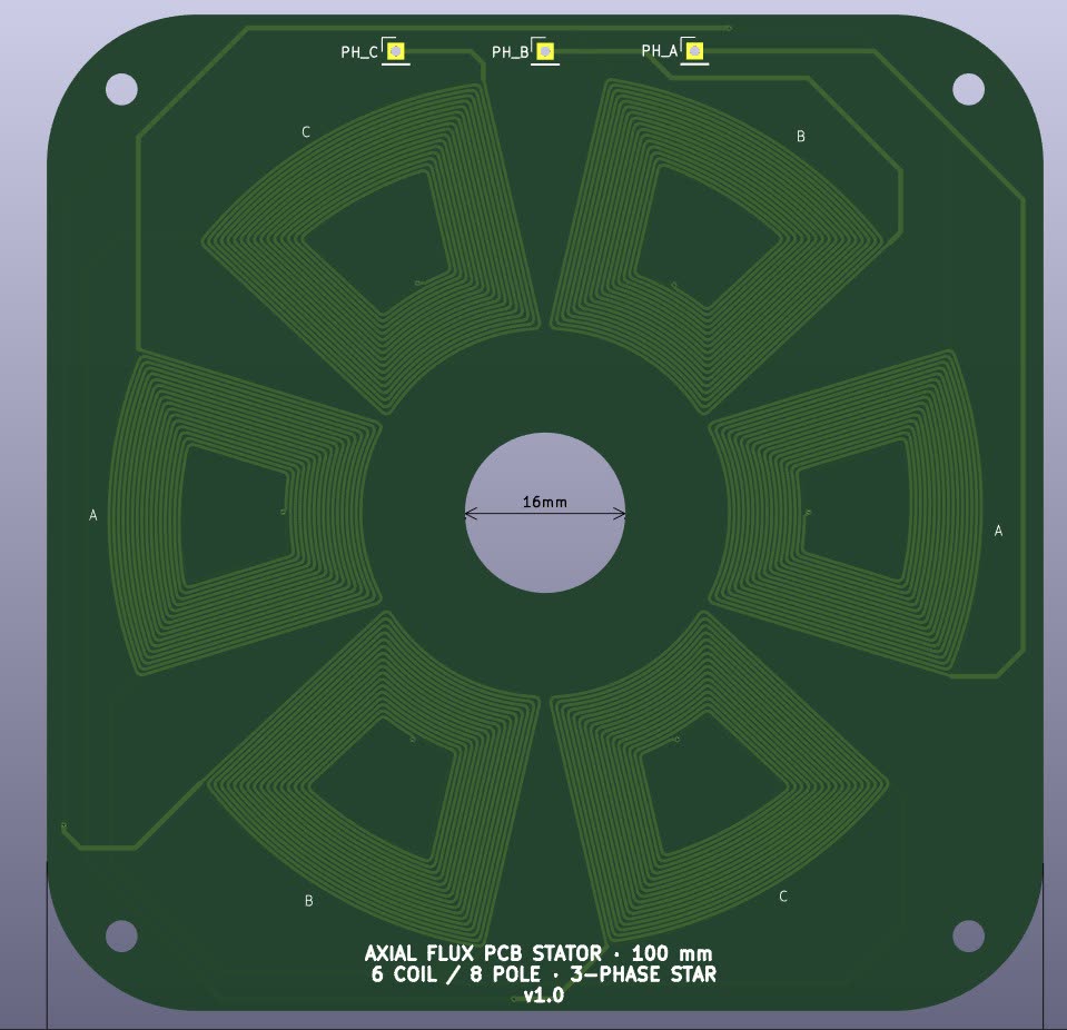
No iron anywhere except the magnets. That has one lovely consequence: there is nothing for the magnets to grab, so cogging torque is exactly zero. It starts smoothly from any position. It also means the whole magnetic problem is linear, which made it much easier to analyse than a normal motor.
simulating it was the actual project
I wanted the torque constant before committing to a design, so I went to FEMM. This is where it got interesting, because FEMM is a 2D solver and an axial-flux motor is not a 2D problem.
In a 2D planar model, current flows perpendicular to the screen. My board is a flat disc, so if you import the top-down copper pattern and energise it, you are pushing current through the 1.2 mm thickness of the board. In the real motor the current runs in the plane of the board and the magnet flux crosses through it. Torque is radial current × axial flux, so the top-down model has the current at 90° to reality. Any number it prints is meaningless.
I spent a while trying to fix geometry that wasn’t broken before I understood this was a limit of the method, not a bug in my file.
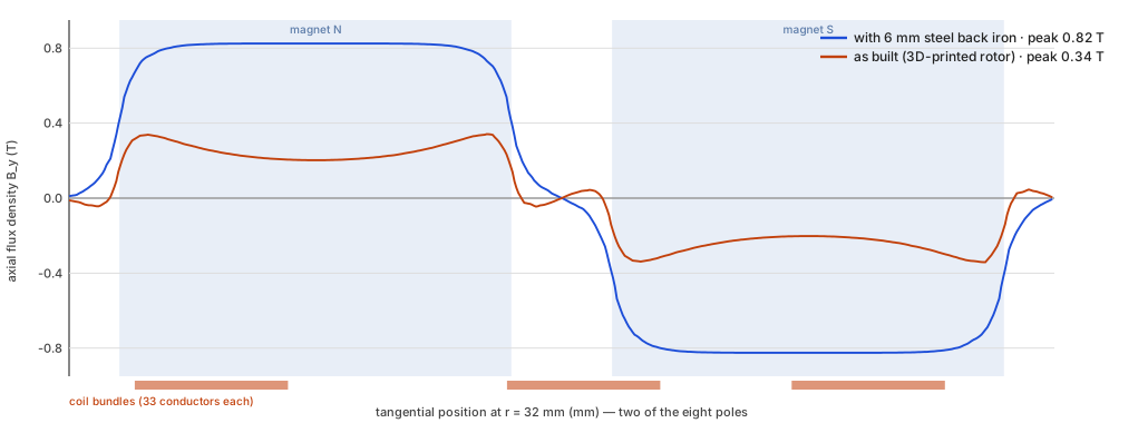
The fix is to stop looking down at the motor and cut it on a cylinder, then unroll that cut flat. Now the out-of-plane direction is the radial direction, which is exactly where the coil current goes. One problem: a round magnet’s width changes with radius, so a single slice can’t represent it. So I took five slices at r = 24, 28, 32, 36 and 40 mm, gave each the true local chord of the 20 mm magnet, and summed the torque.
what it told me
Everything in this table is the model, not the bench:
| plastic rotor | with steel back plates | |
|---|---|---|
| flux at the copper | 0.34 T | 0.82 T |
| torque constant | 40.9 mN·m/A | 135.1 mN·m/A |
| Kv | 496 rpm/V | 150 rpm/V |
| cogging | zero | zero |
The useful finding is the gap between those two columns. My design had quietly assumed steel behind the magnets to return the flux. With a printed carrier the only return path is back through air across a 25 mm pole pitch, so most of what the magnets produce never reaches the copper. The 3D-printed rotor gives away 3.3× of the torque. Two steel discs, about 6 mm each, get it back — and cost nothing in copper, current or board area. (I checked 3 mm first and it saturates badly, so 6 mm is the honest number.)
Finding that before the design was frozen is the whole reason I bothered with the simulation.
and then I built it
The motor comes out at 350 rpm/V. I had designed for about 176, and the model predicted 496 for the rotor I actually printed.
So reality landed between the two, and — this is the part I did not expect — it landed on the good side of the model. A lower Kv means a higher torque constant, so the real motor makes about 1.4× the torque per amp that my unrolled model said it would.
That’s the opposite direction from the error I’d warned myself about. A 2D method has no radial end effects and no leakage around the coil end-turns, and both of those reduce real torque, so I expected to come in 10–20% below the model, not 40% above it. Something in the model is conservative and I haven’t pinned down which thing yet. Candidates I’d check first: the effective magnet area (my chord-weighted slices came out 2.7% high, which is the wrong way), the 0.5 mm air gap being tighter in the assembled stack than I specified, and the ±0.04 T of mesh noise in the low-field gaps between magnets.
I’d rather write that down than round it off. The number I’d quote for this motor is 350 rpm/V, because that’s the one that came off the bench.
The other thing worth knowing: the traces are 0.30 mm × 35 µm, which works out to 95 A/mm² per amp. That is a very high current density, so this motor is thermally limited, not magnetically limited. The 23 W figure at 1 A is not a continuous rating — a bare board this size passively cooled handles maybe 2–3 W, so realistically 0.3–0.35 A per phase and 12–14 mN·m continuous as built. It’s a real constraint and it’s the one I’d design against next time.
checking my own work
Getting a number out of FEA is easy. Getting one you believe is not, so I closed the loop three ways:
- my own analytic ∫J×B, FEMM’s Lorentz volume integral, and FEMM’s Maxwell stress tensor on the rotor — all three agree within 5%
- rotor force vs stator force, which Newton says must be equal and opposite — 3.0%
- I measured the fabricated copper by cutting the real exported polygons with a circle at r = 32 mm: 33 conductors per coil, 0.3010 mm trace width, 0.4714 mm pitch. The model said 33, 0.30 and 0.47.
That last one is the check I trust most, because it compares the model against the board that actually got made rather than against the parameters I typed in.
I also extracted each phase’s electrical angle from the solved field instead of assuming it, which is how I caught a genuine mistake: adjacent coils are 60° apart mechanically, but with four pole pairs that’s 240° electrically, so the phase sequence is reversed from what I’d assumed. My first torque number came out as zero because all three phases were cancelling. Assuming that one would have cost me a rebuild.
All of which made the checks agree with each other — and the built motor still came out 40% off, in the direction the method said was impossible. Internal consistency is not accuracy. Worth remembering.
next
Measure the actual air gap in the assembled stack and check the board doesn’t bow more than the 0.5 mm it’s supposed to hold — that’s my first suspect for the 350-against-496 gap, and it’s the cheapest one to rule out. Then the steel back plates, then re-check thermals before I believe any current above 0.35 A. If I still need better than ±15% after that, it needs a 3D solver; FEMM can’t take me further.
made with
- KiCAD
- FEMM
- Python
- magnetostatic FEA
- Lua
- DXF
- N42 magnets
- 3D printing